 Português
 Español
 Français


Initial considerations
To ensure that the concrete pavement adequately performs its functions throughout its service life, it is essential to consider various aspects related to design and construction, such as slab thickness, supporting soil, and joint spacing. Paying attention to these factors allows the pavement to operate efficiently, minimizing maintenance costs.
For pavement design, not only the Ultimate Limit State (ULS) is considered, but also the Serviceability Limit State (SLS), which influences the usability of the structure. The SLS considers the number and width of cracks, as well as deflection limitation, which intrinsically results in usability under the SLS. The theoretical ultimate strength is calculated according to the guidelines of "TR34 4th edition," the standard "EN1992 - Design of Concrete Structures," and the Eurocode EN1990 - Basis for Structural Design.
According to Eurocode EN1990, the safety factors to be used for loads are:
- 1.35 (γG) for permanent actions
- 1.5 (γQ) for variable actions.
The use of steel load transfer bars with adequate strength is recommended, in compliance with the European standard EN10025. For more aggressive environments, corrosion-protected bars may be used as specified by the project.
When defining the joint layout, proper spacing must be ensured so that the maximum opening does not exceed 20 mm.
Construction/Expansion Joints
Expansion joints are prefabricated and form integral part of the pavement, ensuring a continuous and damage-free floor. They consist of the following components:
- Upper Bar: Protects the slab edges (e.g., 40mmx10mm bar, 50mmx5mm wavy bar, or 6 mm sheet with a wavy cut, depending on the type of joint).
- Formwork Sheet: Defines the concrete limits and supports the load transfer bars.
- Plastic Cartridge/Sleeve: Allows the necessary slab movements independently from the adjacent panel (except vertical movement).
- Anchoring: Ensures a solid connection between the joint components and the concrete.
The advantages of using expansion joints include:
- Slab Edge Protection: Prevents concrete disintegration.
- Concrete Pour Stop Function: Facilitates the construction process.
- Efficient Load Transfer: The ALPHA MGSI® joint, with six load transfer bars per 3 meters
- Accommodation of Slab Movements: Compensates for shrinkage effects, temperature variations, and other factors.
The various joint components can be galvanized or made of stainless steel, according to project specifications. Additionally, compressible material can be incorporated between the upper bars to accommodate potential material expansions. The joint is considered to have 100% efficiency, meaning that 50% of the applied load is transferred to the adjacent slab. However, a 5% to 10% loss may be admitted due to gaps that can develop between the load transfer bar and the concrete as a result of repeated loads. The remaining load is transferred directly to the pavement sub-base. It is essential to understand the characteristics of the sub-base, particularly the reaction modulus (k), as this value directly influences the number of load transfer bars required to distribute the load to the adjacent slab. The use of metallic fibers in the concrete composition should not be considered when calculating the load transfer resistance mechanisms of the joints. The applicable safety factors for materials are
- 1.5 for concrete
- 1.15 for steel.
MGSI® construction/expansion joints hold a European Technical Assessment (ETA) and CE marking, ensuring compliance with the Construction Products Regulation (EU) No. 305/2011.
Joints between adjacent slab panels must be correctly executed to ensure effective load transfer, thus limiting differential deformations between panels. If this transfer is not ensured, there will be issues associated with the impact of wheeled vehicles on the edges of the slabs. In the case of slabs supported by the ground, the number of effective transmission plates is calculated as 0.9l for each side of the applied load, where l is the relative stiffness radius calculated according to point 7.5 of TR34 4th edition. A load transfer greater than 50% is not allowed. The plate immediately beneath the load assumes the highest load value, and this value decreases linearly for the remaining plates. If a second load exists at a distance of less than 0.9L, the overlap of stresses should be considered.
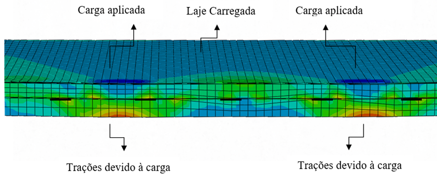
The stiffness modulus of the sub-base layer has a significant influence on the value of L, meaning the higher it is, the smaller L will be, and thus fewer transmission plates will support the load. This publication is the result of a comprehensive review of all aspects of floor design and construction by a multidisciplinary team of engineers, contractors, materials specialists, and users.