Português
 Español
 Français


Joints in Concrete Floors
Recognized worldwide as a relevant publication, this fourth edition brings us updated information focused on the design and construction of concrete pavements.
As far as MGSI and its technical department are concerned, the 4th edition of this guide brings new methodologies for calculating slabs reinforced with metal fibers and new advice on the use of joints in concrete pavements.
Omega Joints
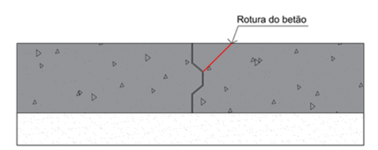
When it comes to joints, once again it is confirmed that the use of joints with a continuous load transmission system (point 6.5.2), the so-called omega joints, is completely discouraged due to the problems of concrete rupture that have been occurring on floors. executed with this system.
Sawn joints
Another important consideration is the fact that sawn joints are not recommended in fiber-reinforced floors (point 7.1) unless there are suitable means of load transmission. Saw joints in fiber-reinforced floors, without an adequate load transmission device, run the risk of opening enough for the slab to lose its load-bearing capacity and become a free edge. In this extreme situation, the slab has significant deformations which leads to cracking and damage to the joint edges.
Load transmission
Given that laboratory tests showed that concrete rupture occurred at loads lower than those calculated in accordance with the previous version of TR34, the 4th version contains new information that must be considered when calculating punching shear resistance.
It is established in point 6.5.4 that the improvement provided by the fibers in puncture resistance cannot be taken into account. The calculation of punching resistance is therefore only carried out considering simple concrete, which leads manufacturers of joints with load transmission systems to reformulate the technical specifications of their products.
Cracking
In addition to the structural resistance of the pavement, the designer must minimize the opening of cracks in the pavement. The only way to guarantee a crack-free pavement is to consider a post-tensioned pavement, which results in higher construction costs. That said, all necessary precautions must be taken to ensure that the floor construction is as correct as possible to limit the opening of cracks.
Jointless floors
Since concrete will always shrink, it is not possible to completely dispense with the use of joints. However, in order to avoid the problems associated with sawn joints, areas separated by joints can be concreted every 35m. This construction method is usually associated with the use of metal fibers although a combination of mesh and fibers can be used. In this case, considering a crack opening of around 0.5mm/m, a joint that has sufficient load transmission for opening values of 18mm must be taken into account.
TR34 4th edition indicates some points that must be respected in order to minimize cracking (point 11.1):
- Control the leveling of the sub-base;
- Use of desolidarization membrane with the sub-base;
- Optimize the mixture used for concrete;
- Careful with the layout and type of joints;
- Use of desolidarization joints with singular restriction points (pillars, machine foundations, etc.).
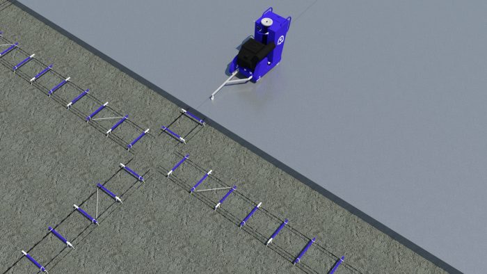
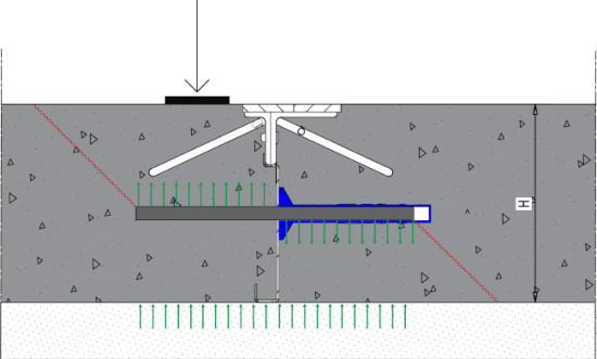
Load transfer
in joints
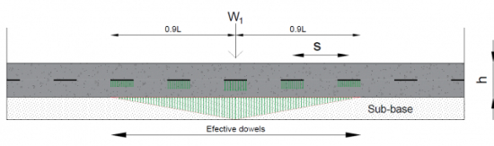
Joints between adjacent slab panels must be correctly executed to ensure effective load transfer, thus limiting differential deformations between panels. If this transfer is not ensured, there will be pathologies associated with the impacts of vehicles on the edges of the slabs.
In the case of slabs supported by the ground, the number of effective transmission plates is calculated as 0.9l for each side of the applied load, where l is the radius of relative stiffness calculated according to point 7.5 of TR34 4th edition
A load transmission of more than 50% is not possible. The plate immediately below the load assumes the highest load value and this value decreases linearly for the other plates. If there is a second load that is less than 0.9L away, voltage overlap must be considered.
The rigidity modulus of the sub-base layer has an extreme influence on the value of L, and the higher it is, the lower L will be, meaning fewer transmission plates will support the load.
This post is the result of a thorough review of all aspects of floor design and construction by a multidisciplinary team of engineers, contractors, materials experts, and users.